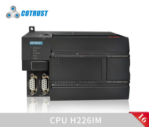
CPU H226IM 24VDC


128 KB de memoria de programa + 128 KB para librerías de funciones, 64 KB de memoria de datos + 100 KB de memoria de datos permanente, alimentación 24 VCC, 14DI / 10DO transitor 0,5 A, 2 puertos PPI / FPORT, 1 puerto Ethernet, 3 salidas de pulsos de 100 kHz (Pulse/Dir) o 2×20 KHz (PTO/PWM). Funciones de Motion Control Single Axis (control posicionamiento, control velocidad, etc.), interpolación de arco / línea recta, función de interpolación continua. Almacenamiento de datos permanentemente. Soporte control analógico, tarjetas de expansión CAN y RS485, compatible con protocolo S7.
Performance Parameters
| Physical Features | |||||||||||||||
| Dimension(W×H×D) | 137×80×62mm | ||||||||||||||
| Power consumption | 7W | ||||||||||||||
| Program memory | 128K+64K+64K | ||||||||||||||
| Data memory | 64KB+100KB,Data permanent stored | ||||||||||||||
| Maximum number of expansion modules | 7 | ||||||||||||||
| Maximum digital | 128DI/128DO(expand CAN expansion board up to 640DI/640DO) | ||||||||||||||
| Maximum analog | 32AI/32AQ(expand CAN expansion board up to 194AI/194AO) | ||||||||||||||
| Data stored | FlashROM Data permanent stored | ||||||||||||||
| Power supply features | |||||||||||||||
| Rated input voltage | DC24V | ||||||||||||||
| Impulse current | 28.8VDC,12A | ||||||||||||||
| Isolation (field and logic) | None | ||||||||||||||
| Hold time (power off) | 10ms above | ||||||||||||||
| Sensor +24V power output | Voltage range:20.4~28.8VDC | ||||||||||||||
| Rated current:300mA | |||||||||||||||
| Maximum ripple noise (<10MHz) :<1V peak-to-peak value | |||||||||||||||
| Isolation (sensor and logic):None | |||||||||||||||
| Power alarm | when it is lower than 15V, the alarm bit SM195.1 | ||||||||||||||
| Regular features | |||||||||||||||
| Total timers | 512 | ||||||||||||||
| 1ms | 4 | ||||||||||||||
| 10ms | 272 | ||||||||||||||
| 100ms | 236 | ||||||||||||||
| Counters | 256 | ||||||||||||||
| Accumulators | 4 | ||||||||||||||
| Memory bit | 256bit | ||||||||||||||
| Local storage(L) | 64 bytes independent | ||||||||||||||
| Sequence control relay(S) | 256 bit | ||||||||||||||
| Time interrupt | 2*1ms resolutions | ||||||||||||||
| Edge breaks | 8 | ||||||||||||||
| Boolean operation execution time | ≤0.15us | ||||||||||||||
| Floating operation execution time | ≤6.2us | ||||||||||||||
| Real time clock | Built-in | ||||||||||||||
| BD expansion board port | One ,BD expansion board supports RS485 expansion board, CAN expansion board, and analog expansion board | ||||||||||||||
| System indicator | SF indicator (red) | ON:Program error,OFF:Normal | |||||||||||||
| DIAG indicator (orange) | ON:Program control,OFF:Normal | ||||||||||||||
| RUN indicator (green) | ON:running,OFF:stopped | ||||||||||||||
| STOP indicator (orange) | ON:stopped,OFF:running | ||||||||||||||
| RMC indicator (green) | ON:remote control is connected,OFF:remote control is disconnected | ||||||||||||||
| LNK/ACT indicator (green) | ON:Ethernet connection,Blinking: Transmission ,OFF:disconnect | ||||||||||||||
| Run switch | RUN/STOP | ||||||||||||||
| External battery port | Special battery card | ||||||||||||||
| Programming card | Support | ||||||||||||||
| Integrated communication capabilities (PPI/ free port) | |||||||||||||||
| Communication interface | 2 Communication port: PORT0:PPI/free port,standard RS485 PORT1:PPI/free port,standard RS485 After the RS485 expansion board is plugged in and restarted, PORT0 (RS485, PPI communication port) PORT1 (RS485, PPI/ free port), FPORT0 (free port) |
||||||||||||||
| Baud rate(baud) | 9.6k、19.2k and 187.5k | ||||||||||||||
| Free port baud rate(baud) | 1.2k ~ 115.2k | ||||||||||||||
| Maximum number of stations | 32 stations per segment, 126 stations per network | ||||||||||||||
| Maximum number of main stations | 32 | ||||||||||||||
| Point-to-point (PPI master mode) | Yes(NETR/NETW),With a maximum of 8 connections and a maximum communication of 200 bytes per connection | ||||||||||||||
| MPI connect | 8(1PG/1OP),2 reserved | ||||||||||||||
|
Maximum cable length per section Use an isolated repeater No isolated repeater is used |
The baud rate is 1000 m at 187.5 K and 1200 m at 38.4 K 50m |
||||||||||||||
| Ethernet Communication | |||||||||||||||
| Communication port | 1 Standard Ethernet port | ||||||||||||||
| Communication standards | IEEE802.3 standards | ||||||||||||||
| Transmission speed | 10Mbps/100Mbps adaptive | ||||||||||||||
| Adaptive cross-connect | Support | ||||||||||||||
| Hardware interface | RJ45 | ||||||||||||||
| Protocol Type |
UDP/TCP protocol Supports UDP_PPI, MODBUS_TCP, Socket, and S7 protocols, Ethernet communication between PLCS, and MiCo Ethernet programming. |
||||||||||||||
| Configuration mode |
Ethernet port search PLC,support the mouth download system configuration. |
||||||||||||||
| Maximum number of connections | 8 UDP/PPI connections, no master or slave | ||||||||||||||
| 8 TCP/Modbus connections, no master or slave | |||||||||||||||
| 4 Socket connections, 2 UDP, 2 TCP | |||||||||||||||
| 8 S7 protocol, no master and slave, COTRUST PLC only as slave station | |||||||||||||||
| Maximum single data transmission | Up to 200 bytes for UDP_PPI transmission. | ||||||||||||||
| Up to 240 bytes are used for ModBus_TCP transmission. | |||||||||||||||
| Up to 512 bytes is used for Socket transmission | |||||||||||||||
| Up to 200 bytes for S7 transmission | |||||||||||||||
| Startup time of network port | 5 to 10 seconds. The startup time varies depending on the network environment. | ||||||||||||||
| Indicator | RMC | On: The remote server is successfully connected | |||||||||||||
| Off: The remote connection is disconnected or the remote function is disabled | |||||||||||||||
| LINK/ACT | On: The hardware of the network port is connected | ||||||||||||||
| Blinking: Data is being exchanged | |||||||||||||||
| Off: The hardware of the network port is disconnected | |||||||||||||||
| The length of the communication cable | 100M,cable type is CAT5e or above | ||||||||||||||
| Isolation | Communication isolation | ||||||||||||||
| IP address reset function | Five consecutive times within two seconds | ||||||||||||||
| Upgrade Firmware function | Use MagicWorks PLC and MiCo to remotely upgrade firmware from company servers over Ethernet | ||||||||||||||
| I/O Features | |||||||||||||||
| Number of integrated digital inputs | 14 | ||||||||||||||
| Input type | Leak/Source | ||||||||||||||
| Number of integrated digital outputs | 10 | ||||||||||||||
| Output type | Source | ||||||||||||||
| Maximum digital | 128DI/128DO(expand CAN expansion board up to 640DI/640DO) | ||||||||||||||
| Maximum analog | 32AI/32AQ(expand CAN expansion board up to 194AI/194AQ) | ||||||||||||||
| The maximum number of local expansion IO modules | 7 | ||||||||||||||
| Pulse capture input | 14 | ||||||||||||||
| High-speed counters | Total
Uniphase counters AB-phase counters |
6 6×50KHz 4×30KHz |
|||||||||||||
|
Integrated Communication Function (CANopen) – use for CAN communication board model CTH2-CAN-01S2-EB |
|||||||||||||||
| Communication Interface |
1(8 Pin) |
||||||||||||||
| Communication speed(kbps) | 1000 | 800 | 500 | 250 | 150 | 50 | 20 | ||||||||
| Maximum cable length(m) | 25 | 50 | 100 | 250 | 500 | 1000 | 2500 | ||||||||
| Maximum station address | 127 | ||||||||||||||
| Station address range | 1-127 | ||||||||||||||
| Maximum number of master and slave stations | 32 | ||||||||||||||
| Configuration method |
CAN configuration blocks and EDS files |
||||||||||||||
| Maximum digital access | Nomal IO | CANopen IO | |||||||||||||
| Byte | Memory starting address | Byte | Memory starting address | ||||||||||||
| Input | 16 | IB0 | Input | 64 | IB16 | ||||||||||
| Output | 16 | QB0 | Output | 64 | QB16 | ||||||||||
| Maximum analog access | Normal IO | CANopen IO | |||||||||||||
| Channel | Memory starting address | Channel | Memory starting address | ||||||||||||
| Input | 32 | AIW0 | Input | 162 | AIW64 | ||||||||||
| Output | 32 | AQW0 | Output | 162 | AQW64 | ||||||||||
| Integrated Communication Function (CANFree) – Used when extending the CAN communication board | |||||||||||||||
| Communication Protocol | CanFree | ||||||||||||||
| Use method | Supported by internal library instructions | ||||||||||||||
| Digital input features | |||||||||||||||
| Number of interated digital input | 14 | ||||||||||||||
| Input type | Leak/source | ||||||||||||||
| Rated voltage | 24 VDC | ||||||||||||||
| Maximum continuous allowable voltage | 30 VDC | ||||||||||||||
| Logic 1 signal (min.) | 18 VDC,3.0mA | ||||||||||||||
| Logical 0 signal (Max.) | 5 VDC,1mA | ||||||||||||||
|
Isolation (field and logic) Isolation group |
500 VAC,1min | ||||||||||||||
| Simultaneously connected input | 14 | ||||||||||||||
| Maximum cable length | 500m | ||||||||||||||
| Shielding: 50 m (high speed counter input); Unshielded: 300 meters (standard input) | |||||||||||||||
| Digital Output Features | |||||||||||||||
| Number of integrated digital output | 10 | ||||||||||||||
| Output type | Solid-MOSFET,source | ||||||||||||||
|
High speed pulse output |
3*100KHz motion control output(Q0.0,Q0.1,Q0.2) 2*20KHz PTO/PWM output(Q0.0,Q0.1) |
||||||||||||||
| Output frequency (maximum) | 100KHz(Q0.0-Q0.2),1KHz(Q0.3-Q1.7) | ||||||||||||||
| Rated voltage output | DC:24V | ||||||||||||||
| Output voltage range | 20.4-28.8 VDC | ||||||||||||||
| Rated current per point | 0.5A | ||||||||||||||
| Rated current for each common point | 4A | ||||||||||||||
| Leakage current (maximum) | 10µA | ||||||||||||||
| Surge current | 8A,100ms | ||||||||||||||
| Lamp load (maximum) | 5W | ||||||||||||||
| On resistance (contact) | typical 0.3Ω,the max 0.6Ω | ||||||||||||||
|
Delay |
Off to on:2us(Q0.0, Q0.1, Q0.2),15us | ||||||||||||||
| on to off:10us(Q0.0, Q0.1, Q0.2),130us | |||||||||||||||
| Output of simultaneously connected | 10 | ||||||||||||||
| Parallel output | Only when the outputs are in the same group | ||||||||||||||
| Maximum cable length |
Shielde |
500m | |||||||||||||
| Unshielded | 150m | ||||||||||||||
También te puede interesar…